


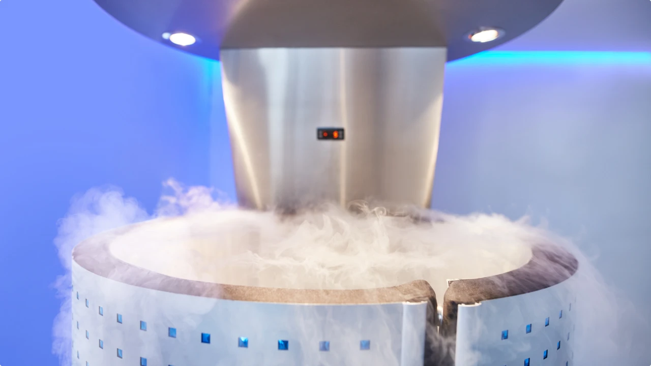
Cryogenic Fluid Transfer: Engineering Magnetic Drive Pumps for Ultra-Low Temperatures
An engineering analysis of sealless magnetic drive pumps in cryogenic applications, focusing on metallurgy, thermal contraction, eddy current mitigation, and NPSH management for liquid nitrogen and argon.
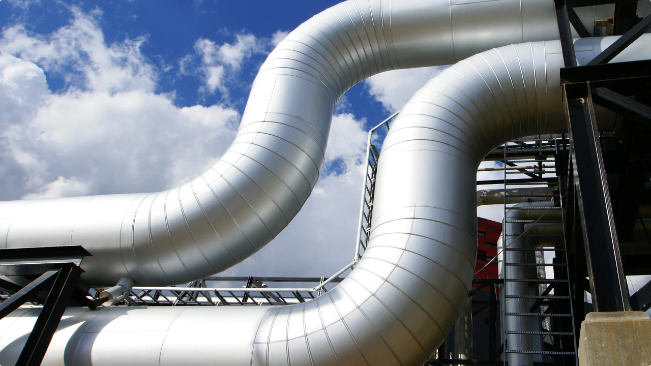
High-Temperature Magnetic Drive Pumps: Engineering Design and Selection Guide
A complete engineering guide on high-temperature magnetic drive pumps, detailing thermal management, metallurgical selection, and sealless zero-leakage operations up to 400°C.
How Cold Plate Liquid Cooling Works: Microchannels, Thermal Resistance, and the Roadmap Beyond
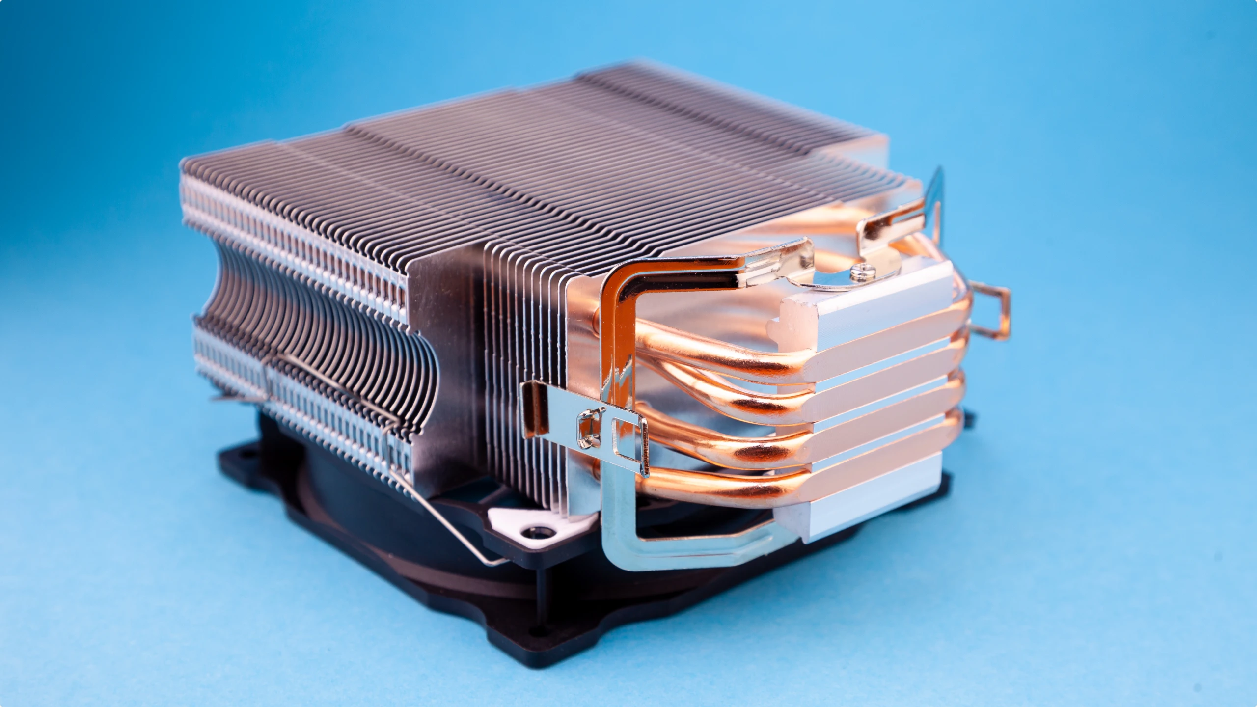
Every degree of cooling performance in a direct-to-chip data center is won or lost on a few square centimeters of machined metal: the cold plate. This component sits directly on the processor, pulls heat through a thermal interface into microchannels of flowing coolant, and hands that heat to the loop that carries it away. The rest of the liquid cooling system, the CDU, the manifolds, the pumps, exists to serve what happens inside this plate. Cold plate engineering has quietly become one of the most consequential design disciplines in AI infrastructure, because package power has climbed from 700 W to

What Is a Rear-Door Heat Exchanger (RDHx)? The Retrofit Bridge Between Air and Liquid Cooling
Every facility manager facing AI hardware in a legacy hall runs into the same dilemma: the racks arriving need 30, 40, 60 kW of cooling, and the room was engineered for a tenth of that. Rebuilding the cooling plant means construction cost, downtime risk, and a building redesign nobody budgeted for. The rear-door heat exchanger exists precisely for this situation. It replaces the standard rear door of a server cabinet with a liquid-cooled coil that captures heat at the rack exit, leaving the servers, the room layout, and most of the existing infrastructure untouched. Market research tracks 83 percent of

Why Air Cooling Hits a Wall: The Physics Behind the Data Center Shift to Liquid
Ask five vendors where air cooling stops and you will get five numbers: 15, 20, 40, 50, even 80 kW per rack. Every one of them is defensible, because each describes a different boundary: a legacy room average, a contained aisle, a close-coupled product, or an active rear door. The confusion disappears once the physics are laid out, because the limit is a moving threshold set by three measurable mechanisms, and all three trace back to one equation. This guide works through the physics of the air wall: why convective heat transfer caps air cooling, where the practical thresholds sit

What Coolant Does a Data Center Use? Water-Glycol, Dielectric Fluids, and the Chemistry That Decides
Ask what liquid runs inside a liquid-cooled data center and the honest answer is: it depends which loop you open. The cold plate loop behind a row of AI servers carries a fluorescent-tinted water-glycol blend with a corrosion inhibitor package. The immersion tank down the hall holds a dielectric fluid that costs ten to thirty times more per liter. A two-phase installation may still be running on chemistry its manufacturer has already announced it will stop making. The fluid is an engineering decision with consequences for thermal performance, pump energy, maintenance intervals, regulatory exposure, and total cost over a ten-to-fifteen-year
What Is a Coolant Distribution Unit (CDU)? How Liquid Cooling Reaches the AI Rack
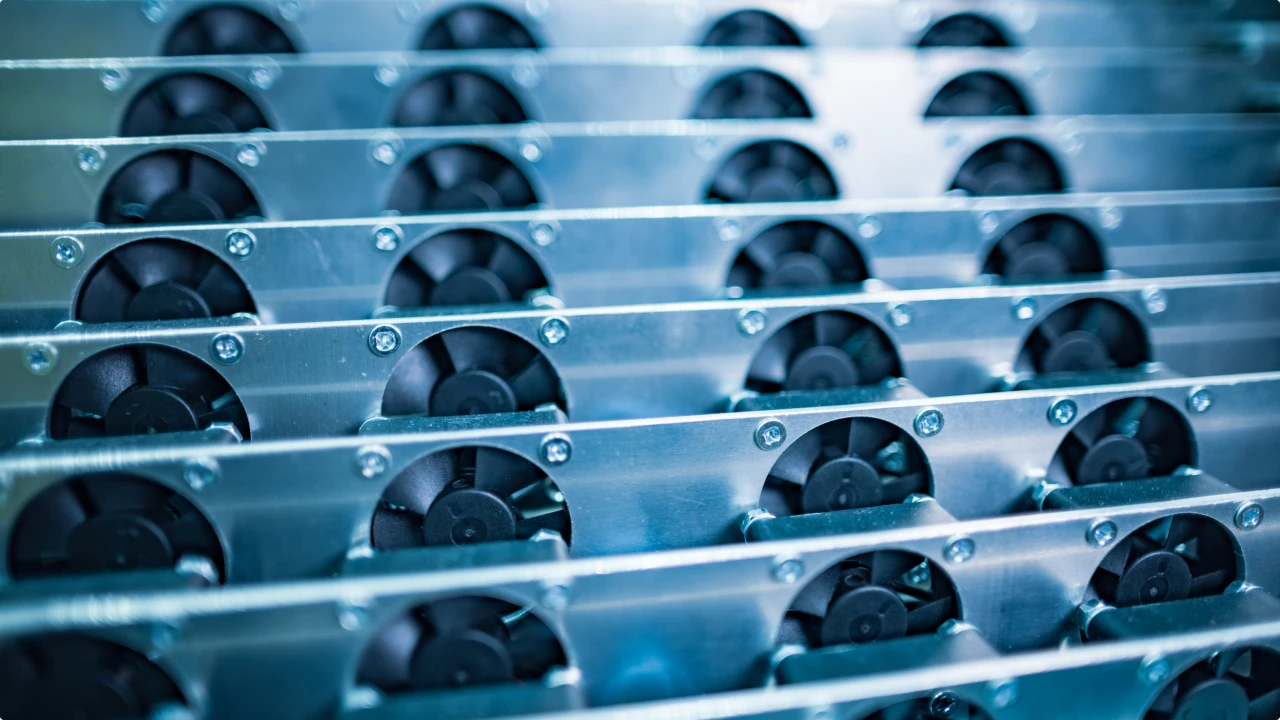
Air cooling ends somewhere around 20 kW per rack. AI racks already run past 100 kW, and announced GPU systems point toward 600 kW per rack within a few product cycles. Liquid moves roughly 3,000 times more heat than air per unit volume, which is why every serious AI deployment now includes a liquid cooling loop, and why one piece of equipment sits at the center of all of them: the coolant distribution unit, or CDU. The CDU decides what temperature, flow, and pressure actually reach the cold plates on the processors, and it keeps the facility's water away from

Direct-to-Chip vs Immersion Cooling: An Engineering Comparison for AI Data Centers
Every AI facility planning discussion lands on the same fork: direct-to-chip cold plates or full immersion. Both move heat with liquid, and both outperform air by an order of magnitude, yet they differ in almost everything that determines project success: how much of the server they cool, what the building must provide, how technicians service hardware, and what the fluid loop demands from its pumps. Vendor comparisons tend to favor whichever architecture the vendor sells. This guide compares the two on engineering terms, with the numbers that decide real projects and the pump and fluid-loop implications that most comparisons skip.How
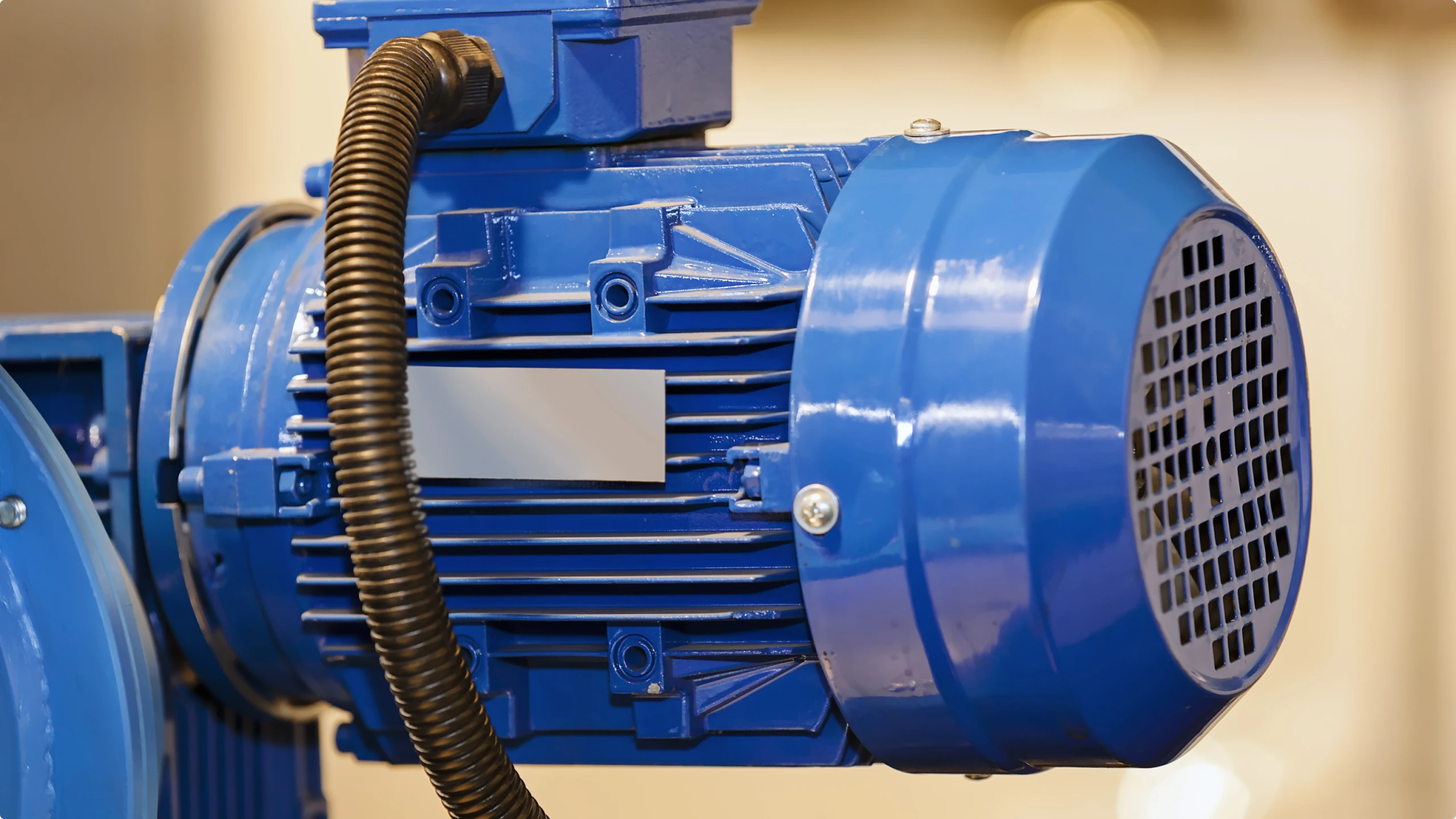
How to Select Explosion-Proof Pumps for Flammable Liquids
Pumping flammable liquids with standard equipment converts a routine transfer operation into an ignition source waiting for fuel. Solvents such as acetone, toluene, MEK, and ethanol release vapors that form explosive mixtures with air at concentrations achievable in any filling station, reactor room, or tank farm. A single arc from a motor winding, a hot bearing surface, or a static discharge from an ungrounded casing is sufficient to ignite that mixture. Explosion-proof pumps eliminate or contain these ignition sources through certified motor protection concepts, antistatic construction, and seal architectures that keep flammable fluid and vapor inside the pressure boundary. This