
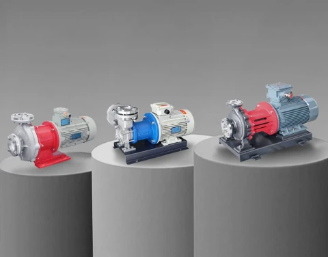



Selecting the correct kinetic pump dictates the efficiency, longevity, and safety of an industrial fluid handling system. For applications requiring the movement of clean liquids, engineers typically choose between a standard centrifugal pump and a vortex pump (also known technically as a regenerative turbine or peripheral pump). While both rely on a spinning impeller to impart energy to the fluid, their internal physics, performance curves, and operational limits are fundamentally opposed. Misapplying these technologies leads to dead-headed lines, destroyed impellers, and melted mechanical seals. This technical guide examines the precise mechanical differences, thermodynamic behaviors, and piping system requirements necessary to specify the correct pump for distinct industrial duties.
Fundamental Mechanics: How Energy is Transferred
The primary distinction between the two designs lies in fluid trajectory. Energy transfer defines pressure capability.
The Centrifugal Mechanism
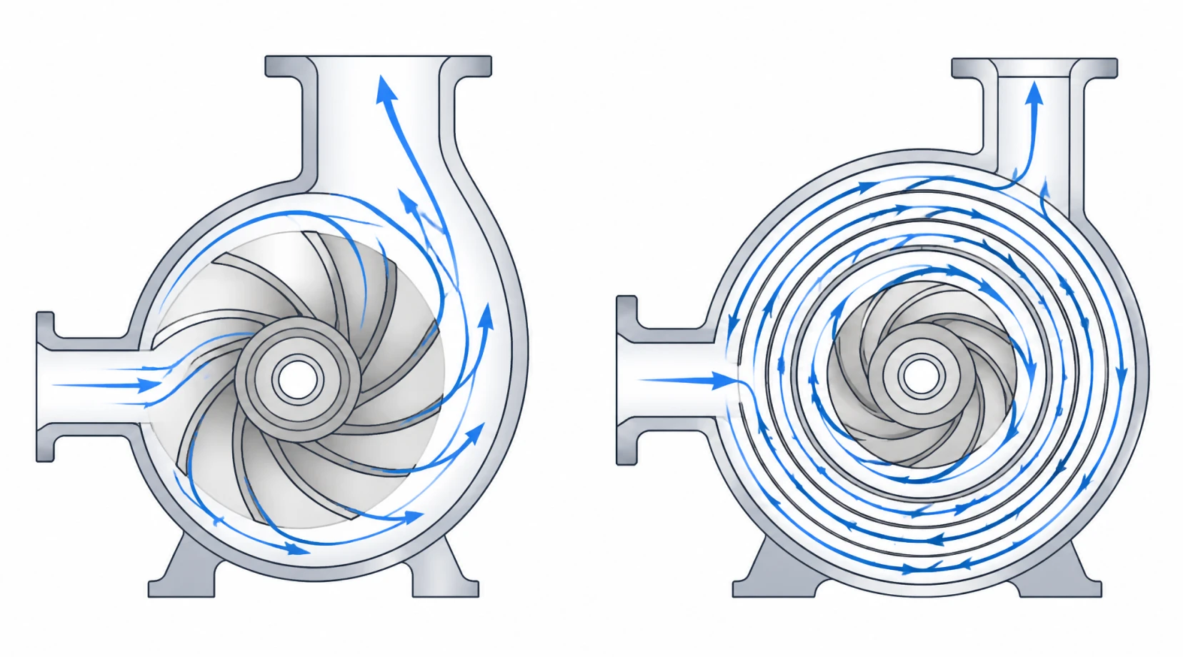
A centrifugal pump accelerates fluid radially. Liquid enters the center (the eye) of the impeller parallel to the shaft. The rotating vanes immediately catch the fluid and fling it outward through centrifugal force into a diverging volute casing. As the fluid travels outward, its kinetic energy (velocity) is converted into potential energy (pressure). Crucially, the fluid passes through the impeller vanes exactly once. This single-pass acceleration is highly efficient for generating massive flow rates but physically limits the amount of pressure (head) a single impeller can produce.
The Vortex (Regenerative Turbine) Mechanism
A vortex pump relies on regenerative action. The fluid enters the peripheral channel of the casing rather than the eye. The impeller features dozens of small, straight radial vanes machined into its outer edge. As the impeller spins, the fluid is dragged along the annular channel. Instead of a single pass, the liquid is thrust outward into the casing, pushed back into the root of the next vane, and thrust outward again. This helical, corkscrew trajectory means the fluid receives kinetic energy pulses repeatedly during a single revolution. This regenerative action functions identically to a multi-stage pump compressed into a single, compact stage, generating extremely high discharge pressure at very low flow rates.
Analyzing the Performance Curves
Performance curves dictate system matching. The Head-Flow (H-Q) and Power (BHP) curves for these two pumps run in opposite directions.
Head and Flow (H-Q) Dynamics
A centrifugal pump exhibits a relatively flat to moderately drooping H-Q curve. If system pressure drops, a centrifugal pump will rapidly increase its flow rate, moving toward the right side of the curve. This makes it ideal for bulk transfer where system resistance is low.
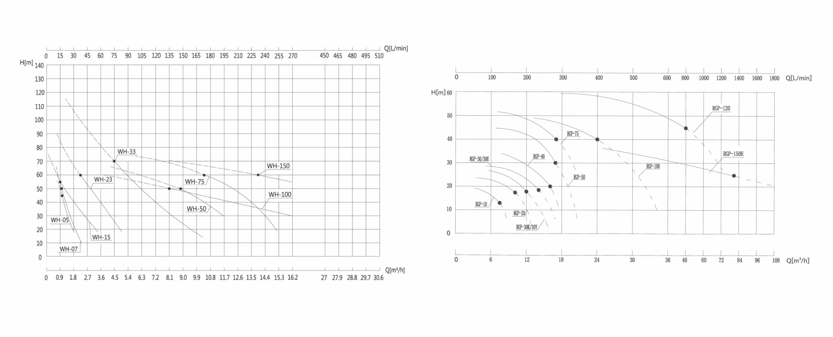
A vortex pump possesses a remarkably steep H-Q curve. Small changes in flow rate correspond to massive shifts in generated head. This characteristic makes the vortex pump exceptionally stable in systems with fluctuating backpressure, such as boiler feed lines. If system pressure spikes, the vortex pump maintains a consistent, steady flow, whereas a centrifugal pump's flow would collapse completely.
Brake Horsepower (BHP) and Power Consumption
The most critical engineering distinction lies in the power curve.
● Centrifugal Power Curve: Power consumption increases directly with flow. A centrifugal pump consumes the least amount of electricity at dead-head (shutoff, zero flow) and maximum electricity at maximum flow.
● Vortex Power Curve: Power consumption increases directly with pressure. A vortex pump consumes its absolute maximum electrical power at shutoff (zero flow). If a downstream valve is closed while a vortex pump is running, the pressure will skyrocket instantly, overloading the motor and tripping the electrical breakers, assuming the casing does not rupture first.
Handling Difficult Fluids: Gases, Viscosity, and Solids
Fluid composition severely restricts pump selection. Not all clean liquids behave identically inside tight hydraulic casings.
Entrained Vapors and Cavitation Resistance
When pumping hot condensates, boiling thermal oils, or volatile chemicals, dissolved gases often break out of the liquid. Standard centrifugal pumps are notoriously sensitive to entrained gas. If gas volume exceeds 3% to 5%, the gas accumulates in the eye of the impeller, causing a complete loss of prime known as vapor lock. The pump spins dry and destroys its mechanical seal.
Vortex pumps possess exceptional gas-handling capabilities. The regenerative turbine action naturally breaks up vapor bubbles and compresses them back into the fluid stream. A well-designed vortex pump can routinely handle fluids with up to 20% entrained gas without losing prime. This makes them the definitive choice for Dissolved Air Flotation (DAF) systems, ozone injection, and pumping liquids near their boiling points.
Solid Particulates and Internal Clearances
To generate high pressure through regenerative action, vortex pumps require microscopic internal clearances between the impeller faces and the casing channel—often as tight as 0.05 mm to 0.15 mm. Because of this, vortex pumps cannot tolerate abrasive solids. Even microscopic grit will rapidly erode the impeller teeth, instantly destroying the pump's ability to generate head.
Centrifugal pumps, particularly those fitted with semi-open or open impellers, utilize much wider clearances. They handle suspended solids, slurries, and abrasives with significantly lower wear rates. If the fluid is dirty, the vortex pump is immediately disqualified from the selection process.
Mechanical Wear and Lifecycle Cost Analysis
The operational lifespan of the equipment relies heavily on managing radial loads.
In a single-volute centrifugal pump, uneven pressure distribution around the impeller creates a heavy radial thrust that deflects the pump shaft. Prolonged operation away from the Best Efficiency Point (BEP) accelerates bearing fatigue and mechanical seal face wear.
Conversely, most industrial vortex pumps feature a symmetrical double-suction or balanced fluid channel design. This symmetrical hydraulic loading neutralizes radial thrust against the shaft. As long as the fluid remains completely free of abrasive particulates, the ball bearings and mechanical seals in a vortex pump often exhibit longer uninterrupted lifespans than those in standard centrifugal units running under fluctuating demands.
Industrial Application Mapping
Equipment specification must align the pump's hydraulic geometry with the exact requirements of the process loop.
Where Centrifugal Pumps Dominate
Centrifugal pumps deliver maximum volume at moderate resistance. They dominate cooling tower circulation, bulk chemical unloading, municipal water transfer, and any process where high flow rates (above 50 m³/h) are mandated. Using a vortex pump for high flow is economically unviable due to its inherent low hydraulic efficiency at larger volumes.
Where Vortex Pumps are the Only Option
Vortex pumps excel in the high-head, low-flow envelope where a centrifugal pump would require multiple, expensive stages.
● Temperature Control Units (TCUs): Pumping thermal oil or hot water through intricate mold channels requires overcoming massive friction at low flow rates. Vortex pumps handle this perfectly while resisting vapor lock from the hot fluid.
● Boiler Feed Systems: Injecting water into a highly pressurized steam boiler requires a steep H-Q curve to ensure flow continues even as boiler pressure fluctuates.
● Clean-In-Place (CIP) Return: Moving aerated caustic fluids back to storage tanks causes standard pumps to cavitate; vortex units handle the aerated mix easily.
Designing the Piping System for Each Pump Type
Standard piping practices for one pump will destroy the other.
Because a vortex pump draws maximum amperage and generates extreme pressure at dead-head, the discharge piping must never be fully closed while the unit is running. It is mandatory engineering practice to install a Pressure Relief Valve (PRV) on the discharge line of every vortex pump, routing the bypass fluid back to the suction tank. If a downstream valve is accidentally closed, the PRV opens to prevent casing rupture and motor burnout.
Centrifugal pumps do not require a PRV to prevent instantaneous over-pressurization, though a minimum flow bypass is often utilized to prevent the trapped fluid from boiling due to mechanical friction if the pump is run dead-headed for extended periods. Furthermore, centrifugal pumps require straight runs of suction piping (typically 5 to 10 pipe diameters) to ensure laminar flow into the impeller eye; vortex pumps are far less sensitive to turbulent inlet conditions.
System Integration and Product Selection
Final specification depends strictly on the intersection of system resistance, required flow rate, and fluid purity. If the system demands massive fluid turnover with low backpressure, a centrifugal pump provides the highest thermodynamic efficiency. If the application involves high-pressure injection, temperature control circulation, or entrained gases at lower flow volumes, the vortex pump provides unmatched stability and vapor-handling capability. For detailed hydraulic curves and material compatibility charts, review our comprehensive range of industrial pumps. Accurate engineering upfront eliminates unplanned downtime and mechanical failures in aggressive processing environments.