


In the vast ecosystem of industrial fluid dynamics, the centrifugal pump stands as the undisputed workhorse. It is estimated that nearly 85% of all pumps installed globally are of this variety. Whether in water treatment plants, chemical processing facilities, or thermal management loops, these kinetic machines are the primary method for transporting liquids.
However, despite their ubiquity, pump failures and inefficiencies often stem from a fundamental misunderstanding of their hydraulic characteristics. Unlike positive displacement pumps that force a fixed volume of fluid through a system, a centrifugal pump relies on velocity and momentum. It is a dynamic machine where the flow rate is variable and dependent on the system's total dynamic head (TDH).
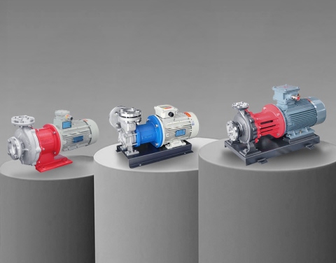
For engineers and procurement specialists, selecting the right unit requires more than just matching a flow rate; it demands a deep understanding of fluid mechanics, impeller geometry, and material compatibility. This guide provides a rigorous technical analysis of the centrifugal pump, referenced against the capabilities of Aulank’s industrial pump series.
Understanding the Rotodynamic Pump Working Principle
To answer "what is a centrifugal pump" technically, we must define it as a member of the rotodynamic pump family. It operates on a simple yet powerful physics concept: Bernoulli’s Principle and the conservation of energy.
The core mechanism involves the conversion of rotational mechanical energy (from an electric motor) into hydraulic kinetic energy, and finally into potential energy (pressure).
- Suction Phase: Fluid enters the pump suction nozzle and is directed into the center of the rotating impeller, known as the "eye."
- Acceleration Phase: The impeller, driven by the shaft, rotates at high speeds (typically 1450 or 2900 RPM). The centrifugal force flings the liquid outward along the vanes. As the liquid moves from the eye to the outer diameter of the impeller, its velocity increases drastically.
- Diffusion Phase: The high-velocity liquid exits the impeller and enters the volute casing. The volute is designed with an expanding cross-sectional area. As the area increases, the velocity of the fluid decreases. According to Bernoulli’s equation, this drop in velocity results in a proportional increase in pressure.
This velocity-to-pressure conversion is what allows the pump to discharge fluid against system resistance. It is crucial to note that a centrifugal pump does not create pressure directly; it creates flow. Pressure is merely the result of that flow encountering resistance (friction and elevation).
Anatomy of a Radial Flow Pump: Key Components
While there are many variations, the standard radial flow pump (the most common type of centrifugal pump) consists of specific wet-end components that dictate its performance and durability.
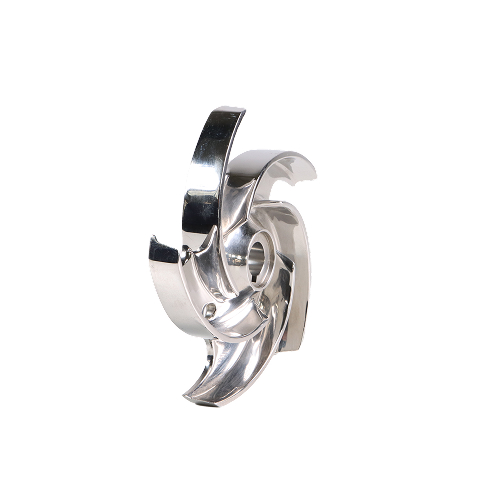
The Impeller: The Heart of the System
The pump impeller design determines the flow and head characteristics.
- Closed Impeller: Features shrouds on both sides of the vanes. This design maximizes hydraulic efficiency and is used for clean liquids. Aulank’s AMC Magnetic Drive Pumps typically utilize this design to ensure high pressure and stability.
- Semi-Open Impeller: Has a shroud on only one side. It sacrifices some efficiency for the ability to handle liquids with a small amount of suspended solids.
- Open Impeller: Vanes are exposed on both sides. While less efficient, this design is necessary for handling slurries or high-viscosity fluids to prevent clogging.
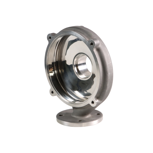
The Volute Casing
The casing acts as the pressure containment vessel. In industrial process pumps, the casing material is selected based on chemical compatibility. Aulank utilizes materials ranging from Cast Iron for general water applications to Stainless Steel (304/316) and Fluoroplastic linings (PFA/F46) for aggressive chemical handling.
The Shaft and Sealing System
The shaft transmits torque from the motor to the impeller. The point where the shaft enters the casing is the primary leak path. Here, mechanical seal types play a pivotal role.
- Single Mechanical Seal: Standard for water and non-hazardous fluids.
- Double Mechanical Seal: Used with a barrier fluid for abrasive or hazardous media.
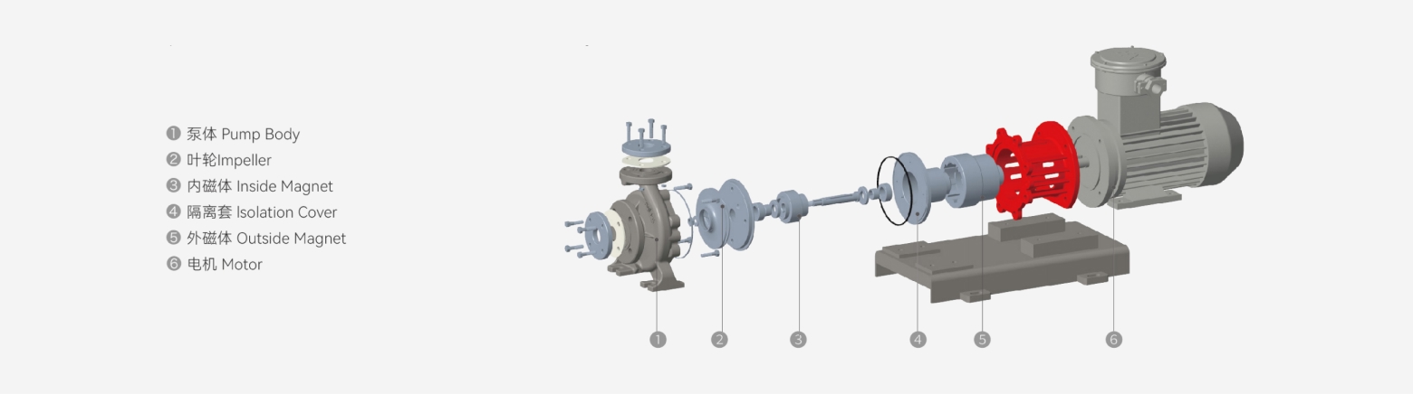
- Magnetic Coupling (Sealless): As seen in the Aulank AMC series, the shaft does not penetrate the casing. Torque is transmitted magnetically, ensuring zero leakage.
Classification of Kinetic Pumps by Hydraulic Design
When sourcing an industrial kinetic pump, engineers will encounter various subclassifications. Understanding these distinctions is vital for proper pump sizing.
Single-Stage vs. Multistage Pumps
- Single-Stage Pumps: Feature one impeller. They are ideal for high-flow, low-to-medium head applications. This is the most common configuration for general transfer duties.
- Multistage Pumps: Feature multiple impellers in series. The discharge of the first impeller enters the suction of the second. This design builds immense pressure, making it a competitor to Aulank’s high head vortex pumps (WK Series) in certain overlapping ranges. However, multistage centrifugal pumps are generally bulkier than their vortex counterparts.
Axial Flow vs. Radial Flow vs. Mixed Flow
- Radial Flow: Fluid exits the impeller at 90 degrees to the shaft. High head, medium flow.
- Axial Flow: Fluid moves parallel to the shaft. These are propeller pumps used for massive flow rates at very low heads (e.g., flood control).
- Mixed Flow: A hybrid design for medium flow and medium head.
For most industrial chemical and thermal applications handled by Aulank, the Radial Flow Centrifugal Pump is the standard selection due to its balance of pressure and capacity.
Analyzing the Centrifugal Transfer Pump Performance Curve
The behavior of a centrifugal pump is graphically represented by its characteristic curve. Unlike positive displacement pumps, which have a vertical flow/pressure line, a centrifugal transfer pump exhibits a curved relationship.
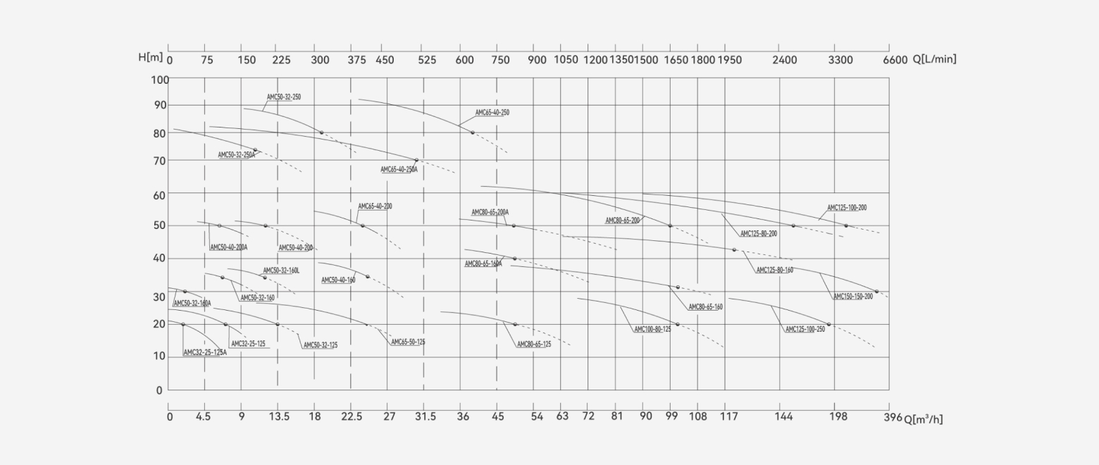
Reading the Curve
- Head-Flow (H-Q) Curve: Typically slopes downward. As the discharge head (resistance) increases, the flow rate decreases.
- Best Efficiency Point (BEP): This is the precise flow rate and head where the pump operates with minimum energy loss and vibration. Sizing a pump to run at its BEP is critical for longevity.
- Shut-off Head: The maximum pressure the pump can generate at zero flow. Running a pump here for extended periods causes rapid overheating and hydraulic instability.
The Affinity Laws
These laws predict how changes in speed (RPM) or impeller diameter affect performance.
- Flow is proportional to speed ($Q \propto N$).
- Head is proportional to the square of speed ($H \propto N^2$).
- Power is proportional to the cube of speed ($P \propto N^3$).
This highlights why utilizing a Variable Frequency Drive (VFD) is the most energy-efficient method for flow control, rather than throttling a valve.
Applications: Where to Use a Dynamic Pump?
The dynamic pump category excels in specific zones where high volume throughput is required.
Chemical Processing
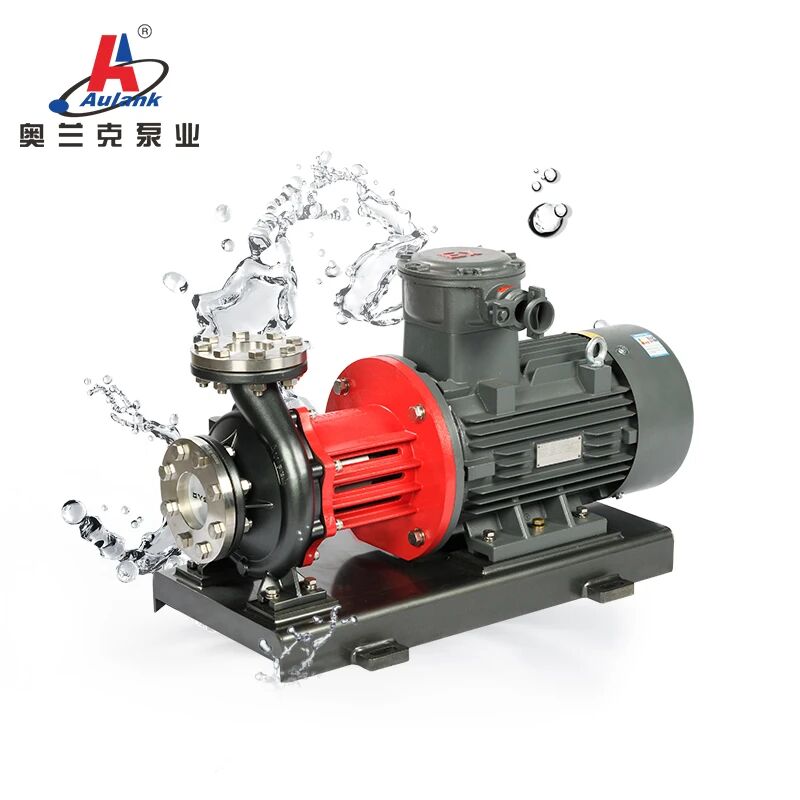
For transferring bulk solvents, acids, or bases from storage tanks to reactors. Here, Aulank’s LMZ Light-Duty Centrifugal Magnetic Drive Pump or AMC Chemical Process Pump are ideal choices. The magnetic drive variant is specifically preferred for corrosive fluid transfer to eliminate seal maintenance.
Thermal Management
In cooling towers and heat exchangers, large volumes of water must be circulated to remove heat. The centrifugal pump provides the high flow rates necessary to maintain turbulent flow in heat exchanger tubes, maximizing heat transfer coefficients.
Water Treatment
From raw water intake to filtration boosting, the centrifugal pump's ability to handle large variances in flow makes it indispensable.
Comparative Analysis: Centrifugal vs. Other Technologies
| Feature | Standard Centrifugal Pump | Vortex (Regenerative) Pump | Positive Displacement Pump |
| Primary Attribute | High Flow / Medium Head | Low Flow / High Head | Constant Flow / High Viscosity |
| Efficiency at Low Flow | Low (Recirculation issues) | High (Ideal range) | High |
| Viscosity Limit | Low (< 500 cPs) | Very Low (< 50 cPs) | High (> 1,000 cPs) |
| Solids Handling | Good (with correct impeller) | Poor (Tight clearances) | Varies (Type dependent) |
| Entrained Gas | Poor (Vapor lock risk) | Excellent (Aulank WD Series) | Good |
Sealing Technologies in Centrifugal Process Pumps
The vulnerability of any centrifugal process pump lies in its shaft seal. In traditional designs, the shaft passes from the motor (atmospheric side) to the impeller (wet side), creating a leakage path.
- Gland Packing: The oldest method, using braided material compressed against the shaft. It requires a steady drip for cooling, making it unsuitable for modern industrial chemical applications due to environmental concerns.
- Mechanical Seals: Consist of a stationary and a rotating face (typically Carbon, Ceramic, or Silicon Carbide). While effective, they require lubrication and are prone to failure if run dry.
- Sealless Magnetic Drive: For hazardous applications, Aulank advocates for the magnetic drive centrifugal pump. An outer magnet ring on the motor shaft drives an inner magnet ring encapsulated in the impeller assembly through a non-metallic containment shell. The containment shell provides a static seal, meaning there is no rotating seal to wear out or leak.
Optimizing Suction Conditions for Centrifugal Water Pumps
A common misconception is that pumps "suck" fluids. In reality, they create a pressure differential, and atmospheric pressure (or tank pressure) pushes the fluid into the pump. This concept brings us to Net Positive Suction Head (NPSH).
- NPSHr: A value provided by the manufacturer (Aulank), indicating the minimum pressure required at the suction port to prevent cavitation.
- NPSHa: The actual pressure available in the system design.
The Danger of Cavitation
If NPSHa < NPSHr, the fluid pressure drops below its vapor pressure. Vapor bubbles form in the eye of the impeller and violently collapse as they move to high-pressure zones. This phenomenon, known as pump cavitation, causes pitting damage to the impeller, excessive vibration, and a distinct noise often described as "pumping gravel."
To ensure reliable operation of a centrifugal water pump, system designers must:
- Keep suction lines short and straight.
- Increase the static height of the supply tank.
- Minimize the number of elbows and valves on the suction side.
Troubleshooting Common Issues in Industrial Flow Pumps
Even top-tier equipment like Aulank’s pumps requires proper operation to maintain performance. Here are common issues encountered with industrial flow pumps:
1. No Flow or Low Flow
- Air Binding: Air is trapped in the volute casing. Centrifugal pumps are not self-priming (unless specifically designed). The casing must be filled with liquid before starting.
- Wrong Direction of Rotation: Especially common after electrical maintenance.
- Excessive Discharge Head: The system resistance is higher than the pump's shut-off head.
2. Excessive Vibration
- Misalignment: The motor shaft and pump shaft are not perfectly aligned.
- Operating off-BEP: Running a pump at very low flows causes internal recirculation, leading to shaft deflection and vibration.
3. Motor Overload
- Fluid Density Change: Centrifugal pumps consume power based on the mass of the liquid moved. Pumping a heavy fluid (like Sulfuric Acid, SG=1.84) with a motor sized for water (SG=1.0) will trip the overload.
- Viscosity Effect: Higher viscosity increases friction on the impeller disk (disk friction loss), drastically increasing brake horsepower requirements.
Conclusion
The centrifugal pump remains the cornerstone of modern industrial infrastructure due to its simplicity, high flow capability, and smooth flow delivery. However, its efficiency and reliability are entirely dependent on correct selection and system integration.
Whether you require a standard stainless steel centrifugal pump for water transfer or a specialized fluoroplastic lined magnetic drive pump (like the AMC-F series) for aggressive chemicals, understanding the underlying physics of the rotodynamic principle is essential.
For high-pressure, low-flow applications where standard centrifugal pumps fall short, consider exploring Aulank’s complementary Vortex Pump Solutions. For standard high-flow requirements, browse our full range of Industrial Centrifugal Pumps to find the model that matches your specific system curve.