


A single NVL72-class AI rack rejects on the order of 120 kW into its coolant loop, with no air-cooled fallback for the GPUs. That dependency makes the circulation pump one of the few components standing between normal operation and a six-figure thermal event. Across a liquid-cooled hall, pumps run continuously at variable speed, push glycol-blended coolant through cold plate channels smaller than a millimeter, and are expected to hold flow stable through years of thermal cycling without leaking a drop onto the floor. The engineering that produces that outcome is specific: a pressure drop budget built from real component data, a coolant chemistry program, a commissioning sequence that leaves no air in the loop, and a redundancy model that survives a pump failure at full load. This guide covers circulation pump engineering for AI data center liquid cooling, from the secondary loop duty profile through sizing, commissioning, and the specification data that gets it right the first time.
Where the Pumps Sit in a Liquid-Cooled Hall
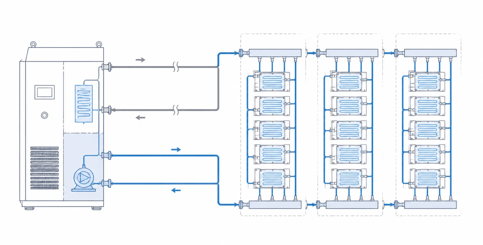
Direct-to-chip deployments concentrate pump duty at three positions:
- CDU secondary loop: the primary circulation position, driving treated coolant from the coolant distribution unit through row and rack manifolds to the cold plates and back. In-rack and row-based CDUs both carry this duty at different scales.
- Facility loop: building-side circulation between CDUs and the heat rejection plant, typically higher flow at lower resistance, served by conventional centrifugal pumps.
- Auxiliary positions: side-stream filtration skids, coolant fill and drain carts, and heat reuse offtakes, each a smaller but real pump duty with its own chemistry exposure.
This guide concentrates on the CDU secondary loop, the position where pump selection decides whether the technology cooling system performs to specification.
The Secondary Loop Duty Profile
The technology cooling loop looks gentle on paper: moderate flow, closed circuit, clean fluid. The operating reality is harder:
- High-resistance circuit: OEM cold plate assemblies specify 40 to 100 kPa of pressure drop at rated flow, and this single component regularly exceeds every other hydraulic loss in the loop combined. Manifolds, hoses, quick disconnects, and valves stack on top.
- Parallel-branch flow starvation: a rack running 40 or more cold plates in parallel sends coolant down the path of least resistance. Without balancing, branches near the supply take excess flow while far branches starve, and the starving branch announces itself as an overheating GPU.
- Glycol physics: the standard propylene-glycol blend (around PG25) protects against freezing and biology, at the cost of higher viscosity and lower thermal conductivity than water. Viscosity climbs further at low supply temperatures, raising both circuit resistance and pump shaft power.
- Continuous variable-speed duty: AI training loads swing power draw in milliseconds, and CDU pumps modulate constantly to hold supply conditions. This is 24/7 duty with thousands of speed transients per day.
- Zero-leak tolerance: the loop operates above live electrical hardware. A dynamic shaft seal is a wear component with a leak path, and in this position its failure mode lands directly on the equipment the loop exists to protect.
Sizing the Pump: The Pressure Drop Budget
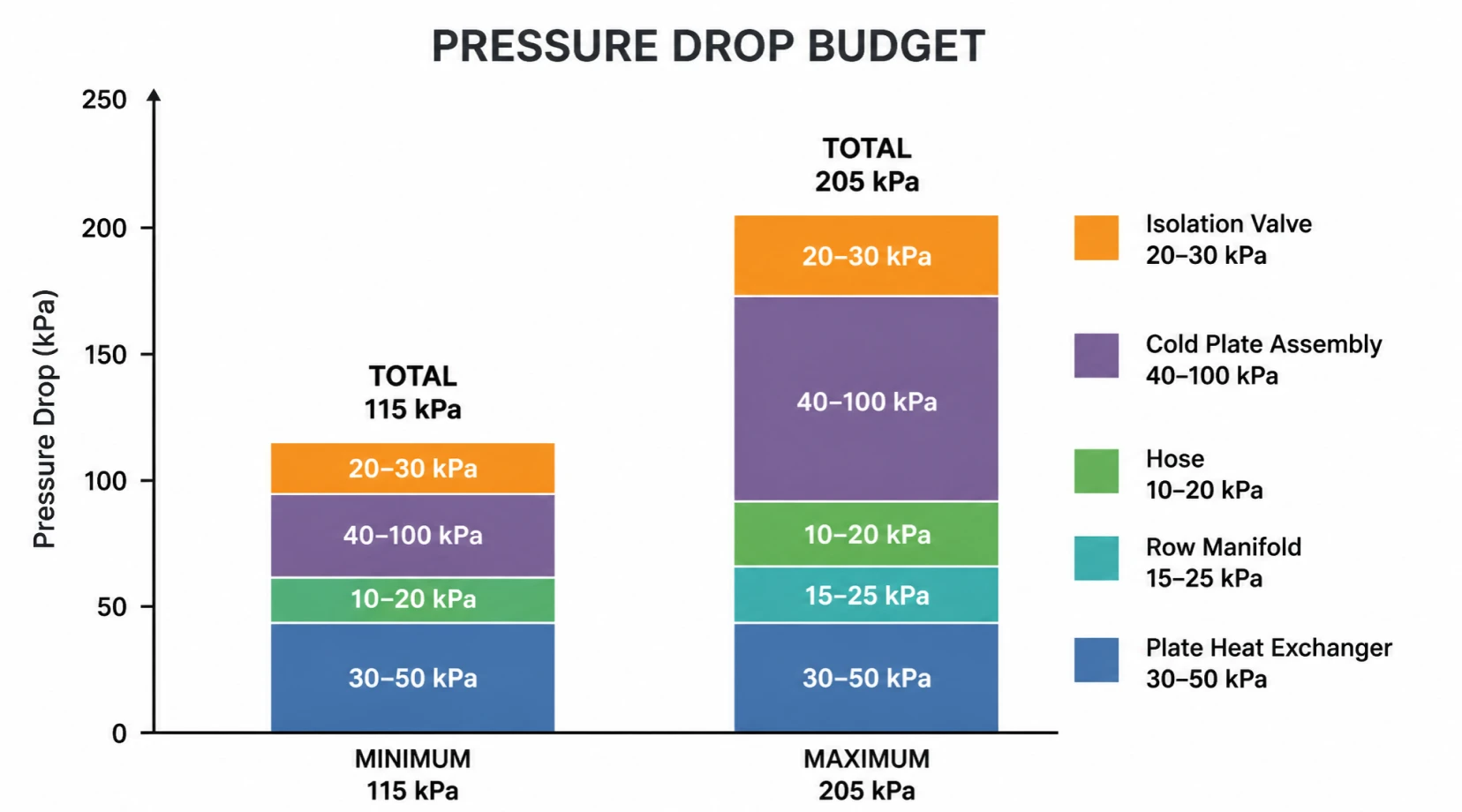
Correct pump head comes from a component-by-component budget, summed at design flow. Typical values for a direct-to-chip secondary loop:
| Component | Typical pressure drop | Data source |
|---|---|---|
| Plate heat exchanger (CDU) | 30 to 50 kPa | CDU vendor datasheet |
| Row manifold, supply and return | 15 to 25 kPa | Manifold design calculation |
| Flexible hoses | 10 to 20 kPa | Hose vendor data |
| Cold plate assembly | 40 to 100 kPa | Server OEM datasheet, at design flow |
| Isolation and balancing valves | 20 to 30 kPa | Valve Cv data |
| Total typical range | 115 to 205 kPa | Sum at design flow |
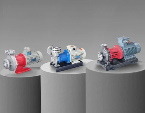
Two rules govern the exercise. First, obtain the cold plate pressure drop at design flow from the server OEM datasheet; estimating this value is the most common and most expensive sizing error, because it dominates the budget. Second, add 10 to 15 percent margin for filter fouling and future GPU power growth, then select a pump whose curve clears the final number with stable operation across the flow range the CDU will command. For the 500 kW row example circulating roughly 21 m³/h at a 20°C temperature rise, the pump specification lands near 250 kPa of head with a flat, stable curve through the modulation range. Vortex magnetic drive hydraulics, as used in the MDW series, deliver exactly this combination of high head at moderate flow, with the detailed selection logic covered in the AI data center liquid cooling pump selection guide.
Coolant Chemistry Is a Pump Specification
Field experience from commissioning programs shows coolant concentration and inhibitor levels varying between totes and fills, and that variation becomes consequential when cold plate channels measure in microns. The chemistry program belongs in the pump specification for three reasons:
- Viscosity sets power: pump curves and motor sizing must reflect glycol viscosity at the minimum supply temperature, which can run well above water values and push an undersized motor into overload on cold starts.
- Materials set life: monometallic loop design, or a validated inhibitor package where metals mix, prevents the galvanic corrosion that sheds debris into microchannels. Stainless steel wetted paths align with the material whitelist most OEMs publish.
- Filtration sets reliability: side-stream filtration at 20 to 50 microns protects cold plates, and rising filter differential pressure becomes part of the resistance the pump must absorb over the maintenance interval.
Leak-tight construction closes the loop on chemistry risk: seal-less magnetic drive containment keeps the coolant in the circuit and the data hall dry, as detailed in the leak-proof pump solutions page.
Commissioning: Where Good Loops Are Made
Commissioning sequences across recent NVL-class deployments converge on four gated stages, and the pump participates in all of them:
- Flush: circulate through bypass hoses at maximum flow, typically 24 hours with side-stream filtration, until filters come out clean. Manufacturing debris left in the loop migrates straight to cold plate microchannels.
- Fill: charge with verified coolant, confirming conductivity, pH, and concentration against specification before it enters the loop.
- Purge: bleed every high point while circulating; trapped air causes the post-commissioning hot spots and pump cavitation that dominate early-life failures. On tall rack manifolds the top trays collect the air and get verified individually.
- Pressure test and baseline: hold at the OEM test pressure with zero decay over the timed window, then record supply temperature, flow, and differential pressure as the commissioning baseline the operations team monitors against for the life of the cluster.
Forward and reverse transfer capability pays for itself at this stage: the MDW series performs fill, drain, and purge operations from a single connection, shortening every commissioning and service event and simplifying the skid by removing dedicated drain hardware.
Reliability: Redundancy That Survives a Real Failure
A stopped pump on a fully loaded AI rack becomes a thermal event within seconds, so redundancy is the baseline, sized N+1 at minimum with automatic switchover. Commissioning should prove it: pull a running pump under load and confirm the standby carries the loop without an alarm storm. Beyond hardware count, reliability comes from the maintenance posture: pumps that can be serviced without draining the loop, condition monitoring on vibration and bearing temperature, and spares staged for the mean time the operation actually tolerates. Seal-less designs remove the highest-frequency failure component from the maintenance calendar entirely, which is why magnetic drive construction has become the default expectation for direct-to-chip secondary loops.
Specification Protocol for CDU and Loop Designers
- Design flow and the full pressure drop budget at that flow, with the cold plate value taken from the server OEM datasheet.
- Coolant identity and concentration, with viscosity at the minimum supply temperature.
- Supply and return temperature range and the modulation profile the controller will command.
- Redundancy model, switchover logic, and the service strategy: whether pumps must be replaceable without draining the loop.
- Wetted material whitelist and filtration rating, to confirm pump construction against loop chemistry.
- Commissioning functions required of the pump: fill, purge, and flush support, and any forward/reverse operation.
Aulank Pump manufactures seal-less vortex magnetic drive circulation pumps for AI data center secondary loops, with stable high head at moderate flow, helium leak-tested containment, water-glycol capability across the full operating envelope, and forward/reverse commissioning functions. Send us your pressure drop budget and coolant data, and our engineering team will return a matched pump with the sizing calculation. Contact us for support on your CDU or loop design.