


Industrial fluid handling operates under a strict binary constraint when moving hazardous media: the chemical must remain entirely within the piping architecture. Pumping lethal, flammable, or highly volatile compounds transforms a minor fluid drip into a critical environmental and life-safety incident. Standard centrifugal pumps rely on dynamic mechanical seals, which require a microscopic fluid film between rotating faces to prevent self-destruction. Consequently, a mechanical seal is a controlled-leakage mechanism. Leak-proof pump solutions eliminate this dynamic leak path entirely. By removing the shaft penetration through the pressure casing, sealless technology provides absolute hermetic containment. This technical document details the mechanical architecture, thermodynamic limits, bearing tribology, and application criteria for specifying zero-emission pump solutions in aggressive chemical processing environments.
The Physical Limitations of Dynamic Sealing
Understanding leak-proof requirements begins with acknowledging the inherent physical limits of traditional sealing. A standard mechanical seal relies on a microscopic gap between a stationary carbon face and a rotating silicon carbide face. The pumped fluid must migrate across this gap, vaporizing as it absorbs friction heat, to lubricate the sliding surfaces. Therefore, normal operation demands fluid emission.
When transferring benign fluids like cooling water, this vaporized weepage is negligible. When transferring benzene, hydrofluoric acid, or isocyanates, this vapor emission crosses the threshold of Permissible Exposure Limits (PEL) established by OSHA and the EPA. Upgrading to API 682 dual-pressurized (Plan 53A/B/C) seal support systems mitigates direct atmospheric leakage but introduces immense mechanical and operational complexity. Dual seal systems require barrier fluid reservoirs, external heat exchangers, nitrogen pressurization, and continuous monitoring. Furthermore, inner seal failure forces the barrier fluid into the process stream, contaminating high-purity chemical batches.
Sealless Containment Architecture
The definitive engineering solution to fugitive emissions is the complete removal of the shaft penetration through the pump casing. Sealless leak-proof pumps achieve this by separating the atmospheric environment from the fluid boundary using a solid, static pressure vessel called a containment shell.
Magnetic Drive Mechanism
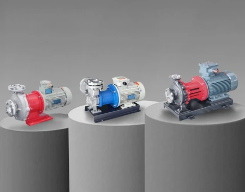
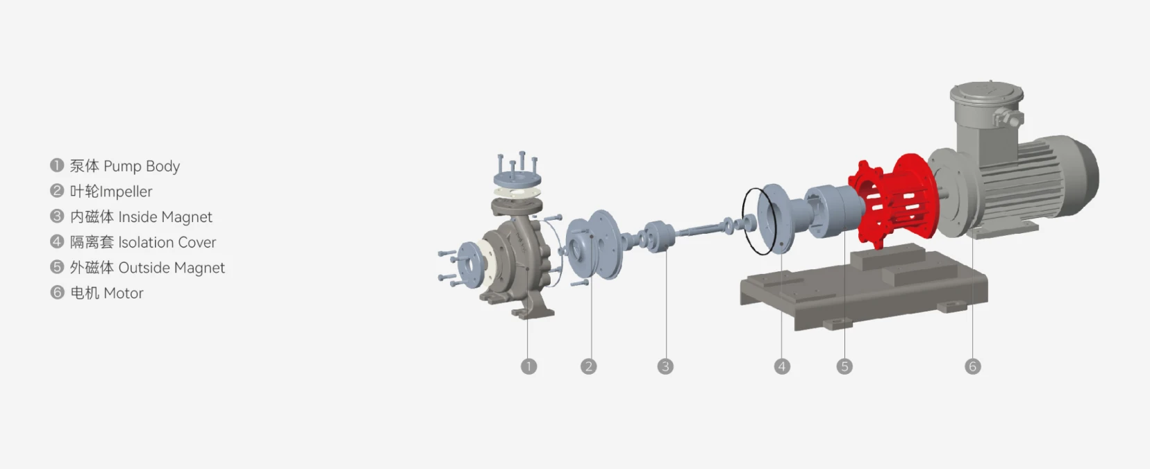
In a magnetic drive (mag-drive) pump, the standard electric motor shaft connects to an outer magnetic rotor operating in the atmosphere. Inside the hermetically sealed fluid boundary, an inner magnetic rotor connects directly to the pump impeller. The static containment shell sits precisely between these two magnetic arrays. As the motor spins the outer magnet, magnetic flux lines penetrate the static shell, forcing the inner rotor to spin synchronously. The hazardous fluid is completely trapped inside the casing. There is no dynamic seal, no barrier fluid, and zero route to the atmosphere.
Canned Motor Pump Alternative
Canned motor pumps achieve similar zero-emission goals by integrating the pump and motor into a single sealed pressure vessel. The motor stator is sealed inside a welded metallic cylinder (the stator can), and the rotor operates directly inside the process fluid. The fluid itself lubricates the rotor bearings and cools the motor windings. Canned motor pumps excel in extreme high-pressure and cryogenic applications where structural limits govern design, though they represent a higher initial capital expenditure and complex maintenance requirements compared to standard mag-drive configurations.
Thermodynamics and Eddy Current Management
Removing the mechanical seal resolves leakage but introduces specific thermodynamic challenges. In magnetic drive pumps utilizing metallic containment shells (typically Hastelloy C-276 or Titanium for chemical resistance), the rotating magnetic field sweeps through the stationary metal. This induces strong eddy currents within the shell.
These eddy currents generate electrical resistance, converting directly into severe localized heat. This thermal energy transfers into the hazardous process fluid circulating in the narrow gap between the inner magnet and the shell. If the fluid is operating near its vapor pressure, this localized heating will cause the liquid to flash into vapor. Internal boiling disrupts the lubrication of internal bearings, causing immediate catastrophic failure.
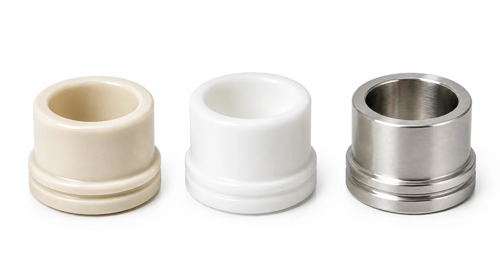
Engineers resolve eddy current heating through precise material selection. For volatile fluids or applications requiring high magnetic torque, non-metallic containment shells fabricated from carbon-fiber reinforced PEEK or industrial ceramics are specified. Non-metallic materials do not conduct electricity, thereby eliminating eddy current losses entirely and preventing heat generation. When metallic shells are mandatory due to extreme system pressures, engineers must calculate and implement precise internal bypass cooling flows to dissipate the generated heat effectively.
Bearing Tribology in Sealless Pumps
Without a drive shaft extending to external oil-lubricated ball bearings, sealless pumps rely entirely on internal journal and thrust bearings submerged within the hazardous chemical. The performance of a leak-proof pump depends on the survival of these internal components.
The industry standard material for internal bearings is alpha-sintered silicon carbide (SiC). SiC provides extreme hardness, near-universal chemical inertness, and zero thermal distortion. However, SiC bearings operate strictly on hydrodynamic principles. They require a continuous, clean fluid film to physically separate the rotating shaft sleeve from the stationary bushing. If the pump loses suction or entrains heavy gas, the hydrodynamic fluid film collapses. Silicon carbide rubbing against silicon carbide without lubrication generates massive friction, shattering the brittle ceramic bearings within seconds. Specifying a leak-proof pump demands stringent process controls to guarantee a flooded suction line and absolutely prevent dry-running conditions.
NPSH and Volatile Fluid Dynamics
Pumping highly volatile hazardous chemicals, such as liquid ammonia, ethylene oxide, or heated solvents, requires strict Net Positive Suction Head (NPSH) analysis. Standard centrifugal pumps calculate NPSHa based primarily on the impeller eye pressure drop. Leak-proof pumps require evaluating a second pressure drop zone: the internal cooling circuit.
A portion of the pumped fluid is diverted over the inner magnetic rotor to lubricate the SiC bearings and cool the containment shell. This fluid experiences friction loss and heat absorption before returning to the main hydraulic stream. If the pressure within this internal circuit drops below the chemical's elevated vapor pressure, internal flashing occurs. This localized cavitation chokes the cooling flow and destroys the bearings, even if the main impeller shows no signs of cavitation. System designers must ensure the available NPSHa significantly exceeds the pump's required NPSHr to suppress boiling within the critical containment shell region.
Navigating Fluid Limitations: Solids and Viscosity
Sealless leak-proof technologies possess strict operational boundaries regarding fluid composition.
● Suspended Particulates: Magnetic drive pumps require microscopic internal clearances to maximize magnetic coupling efficiency and maintain hydrodynamic bearing films. Hard particulates, sand, or pipe scale will rapidly score the SiC bearing surfaces and pack tightly into the magnetic gap, causing the inner rotor to seize. Hazardous fluids containing solids necessitate upstream filtration (typically 50 to 100 microns) or the selection of specialized mechanical seal pumps designed for abrasive slurries.
● Kinematic Viscosity: Magnetic couplings transmit torque based on specific hydraulic loads. As fluid viscosity exceeds 150 to 200 cSt, the internal shear friction against the inner rotor increases drastically. This friction requires more torque from the coupling. If the load exceeds the magnetic bond, the magnets decouple (slip). Operating leak-proof pumps on viscous fluids requires heavily derating the flow performance and upsizing the magnetic coupling mass to handle the sheer stress.
Application Matrix for Zero-Emission Pumping
The capital investment in sealless technology is justified primarily by the severity of the chemical handling risk. Leak-proof pumps dominate specific high-risk sectors:
● Lethal and Toxic Chemicals: Pumping phosgene, sodium cyanide, or hydrogen sulfide requires absolute containment. A static containment shell ensures life-safety protocols are met without the variable reliability of dynamic seals.
● Flammable and Volatile Solvents: Transferring toluene, hexane, or acetone presents severe explosion risks. Eliminating the mechanical seal removes the primary leakage source and the localized friction heat that often acts as an ignition point, strictly satisfying ATEX and hazardous location mandates.
● Pyrophoric and Water-Reactive Fluids: Chemicals like silanes, titanium tetrachloride, or concentrated sulfuric acid react violently upon contact with atmospheric moisture. Hermetic sealless pumps ensure zero cross-contamination with the surrounding environment.
● Fugitive Emission Compliance: Chemical facilities operating under Maximum Achievable Control Technology (MACT) standards utilize leak-proof pumps to guarantee compliance with EPA emission limits, eliminating the heavy overhead costs of monitoring and documenting dual-seal barrier systems.
Material Selection for Extreme Corrosives
The wetted metallurgy defines the pump's survival. For standard hazardous solvents, 316L stainless steel provides adequate containment. However, highly corrosive acids dissolve standard metals rapidly. For duties involving hydrochloric acid, nitric acid, or sodium hypochlorite, a fully non-metallic wetted path is engineered.
Heavy-duty chemical leak-proof pumps utilize a ductile iron armor casing lined with thick ETFE or PFA fluoropolymers. The containment shell is manufactured from carbon-fiber reinforced plastics. This architecture provides the absolute chemical inertness of advanced plastics combined with the structural pressure-retaining strength of cast iron, guaranteeing long-term containment of the most aggressive corrosive media in industrial chemistry.
Mandatory Instrumentation and System Protection
A leak-proof pump is highly reliable but represents a single point of failure if operated outside its hydraulic envelope. Because they cannot tolerate dry running, decoupling, or dead-heading, reliable operation dictates mandatory active instrumentation.
Active power monitors must be integrated into the motor control center. These monitors analyze the true electrical power (kW), detecting the sharp, instantaneous drop in mechanical load associated with cavitation, dry running, or magnetic decoupling. The monitor must be programmed to shut down the motor within milliseconds before the SiC bearings shatter. Furthermore, PT100 temperature RTDs mounted against the containment shell detect abnormal heat rises indicative of restricted internal cooling flow.
Engineering the Solution
Specifying a leak-proof pump requires rigorous calculation of fluid vapor pressure, kinetic viscosity, specific gravity, and chemical compatibility against the physical limits of rare-earth magnetic couplings and ceramic tribology. Proper engineering eliminates fugitive emissions while ensuring decades of uninterrupted process flow. Review our complete chemical pump solutions to align the exact sealless architecture, metallurgy, and fluoropolymer lining with your facility's zero-emission processing mandate.