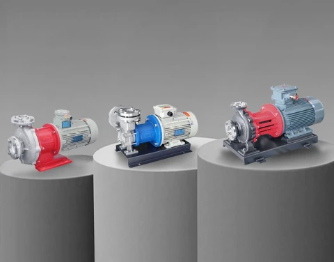


A positive displacement pump moves a fixed volume of fluid per cycle, regardless of system pressure. That single design property — constant volumetric output independent of discharge pressure — explains why positive displacement (PD) pumps remain the standard choice for high-viscosity media, precise dosing, high-pressure low-flow duties, and any process where centrifugal pumps lose efficiency or fail to prime. At Aulank, we manufacture magnetic drive gear pumps and vane pumps in this category, and we've spent years matching pump types to operating conditions in chemical processing, semiconductor, new energy, pharmaceutical, and thermal management systems. This guide covers how PD pumps work, where they outperform centrifugal alternatives, and what engineers should evaluate during selection.

1. What a Positive Displacement Pump Does Differently
A PD pump traps a fixed volume of fluid in an enclosed cavity, then mechanically pushes it from suction to discharge with each rotation or stroke. Output per cycle is locked in by the geometry of the gears, vanes, lobes, screws, pistons, or diaphragms inside the pump head. Speed determines flow. Pressure does not.
A centrifugal pump works on a different principle. Its rotating impeller adds velocity to the fluid, and the volute or diffuser converts that velocity into pressure. As back-pressure rises, flow drops along the pump's characteristic curve. PD pump flow stays nearly flat across the same pressure range — climbing only slightly with speed and dropping marginally due to internal slip.
The practical consequence: if your system needs the same volume delivered every minute regardless of what happens downstream, a PD pump fits. If the system needs large volumes of low-viscosity liquid moved through low resistance, a centrifugal pump runs more efficiently and costs less to operate.

Core Operating Cycle
Every PD pump executes the same three-step cycle, just with different mechanical hardware:
- Suction phase — The pump cavity expands on the inlet side. The volume increase creates a pressure drop, drawing fluid in through the inlet port (or inlet check valve, for reciprocating types).
- Transfer phase — The cavity seals and moves the trapped volume from inlet to outlet. The seal is formed by close clearances between rotating parts and the housing, or by check valves in reciprocating designs.
- Discharge phase — The cavity contracts on the outlet side, forcing fluid into the discharge line at whatever pressure the system demands.
Because the cavity volume is fixed, the pump will keep producing flow until something physically stops it — which is exactly why every PD pump installation requires a pressure relief valve on the discharge side. A blocked discharge will continue to receive flow until the pump, motor, or piping fails.

2. Two Families: Rotary and Reciprocating
All positive displacement pumps fall into one of two motion categories. The choice between them is driven by flow continuity requirements, pressure range, and how the fluid responds to mechanical action.
Rotary PD Pumps
Rotary PD pumps use rotating elements — gears, vanes, lobes, screws, or rollers — to create and move sealed cavities. Flow is continuous and relatively smooth, with low pulsation. Operating speeds typically range from 500 to 3500 RPM depending on type, and most designs handle viscosities from a few cP up to 20,000+ cP.
Rotary types include:
- Gear pumps — Two meshing gears trap fluid between teeth and housing. Compact, accurate metering, suitable for the widest viscosity range.
- Vane pumps — A slotted rotor with sliding vanes creates expanding and contracting chambers. Good for low-to-medium viscosity, self-compensating wear.
- Screw pumps — One or more helical rotors push fluid axially. High flow at high pressure, very low pulsation.
- Lobe pumps — Non-contacting rotating lobes handle solids and shear-sensitive fluids gently.
- Peristaltic pumps — Rollers compress a flexible tube; fluid never touches pump components. Used for sterile, abrasive, or contamination-sensitive media.

Reciprocating PD Pumps
Reciprocating PD pumps use linear back-and-forth motion of a piston, plunger, or diaphragm to alternately fill and discharge a chamber. Inlet and outlet check valves direct flow. These pumps generate the highest pressures in the PD category — 1,000+ bar is achievable with plunger designs — but flow is pulsating and requires dampeners or multiplex configurations for smoothness.
Reciprocating types include:
- Piston pumps — Reciprocating piston in a cylinder, sealed by piston rings. High pressure, moderate flow.
- Plunger pumps — Solid plunger moves through a stationary packing. Higher pressure capability than piston pumps; used for high-pressure water jetting and chemical injection.
- Diaphragm pumps — Flexible diaphragm isolates the fluid from drive components. Leak-free, ideal for hazardous, toxic, or sterile media.
For a deeper breakdown of each pump type with mechanical drawings, parameters, and selection criteria, see our complete classification guide on positive displacement pump types.

3. Performance Characteristics That Matter in Real Systems
The textbook definition gets you partway. What matters in practice is how a PD pump behaves under real operating conditions — when viscosity changes with temperature, when discharge pressure spikes, when the fluid contains entrained gas, or when the suction line is poorly designed. The following characteristics directly affect system reliability.
Constant Flow vs. Pressure Curve
The PD pump performance curve is essentially a vertical line. Flow stays nearly constant from low pressure to maximum rated discharge pressure, with only a small drop caused by internal slip. Slip is fluid that leaks back from the high-pressure discharge side to the low-pressure suction side through internal clearances. Slip increases with pressure differential and decreases with viscosity — meaning a PD pump becomes more volumetrically efficient as the fluid gets thicker, the opposite of centrifugal behavior.
Self-Priming and Lift Capability
Most PD pumps are self-priming. They can evacuate air from a suction line and draw fluid up from below the pump centerline without external priming. Achievable suction lift varies by type: progressive cavity and screw pumps can pull lifts of 7–8 meters under good conditions, while gear and lobe pumps typically manage 4–6 meters. Centrifugal pumps generally cannot self-prime without auxiliary equipment.
Viscosity Handling
This is where PD pumps earn their place in industrial systems. A centrifugal pump's efficiency drops sharply once viscosity exceeds about 100 cP, and most designs become uneconomical above 500 cP due to friction losses on the impeller disk. PD pumps work in the opposite direction — viscous fluid acts as a sealant in internal clearances, reducing slip and improving volumetric efficiency. This is why thermal oil systems, polymer transfer lines, adhesive dosing, and bitumen handling default to PD designs.
Shear and Solids Tolerance
Shear-sensitive fluids — emulsions, latex, certain polymers, food products with delicate structure — degrade when subjected to high impeller velocity. PD pumps operate at lower tip speeds and apply gentler mechanical action, which is why food, dairy, cosmetics, and pharmaceutical processes prefer lobe and progressive cavity designs. For abrasive solids, peristaltic and lobe pumps tolerate particles that would destroy gear teeth or piston seals.
Pulsation
Reciprocating pumps produce pulsating flow as a function of stroke cycle. Single-cylinder designs generate the most pulsation; duplex and triplex configurations smooth it out significantly. Rotary types produce much smoother flow, though gear and vane pumps still generate small ripples at gear-mesh frequency. When pulsation matters — coating uniformity, analytical instrumentation, sensitive downstream equipment — selecting a low-pulsation rotary design or adding pulsation dampeners is essential. Aulank's MDC-X gear pump series, for example, reduces pulsation by up to 70% compared to conventional gear pumps through optimized rotor geometry.

4. PD Pump vs. Centrifugal Pump: When Each Wins
The two pump families overlap less than people assume. The right answer is usually obvious once you list the operating conditions side by side.
| Parameter | Positive Displacement Pump | Centrifugal Pump |
|---|---|---|
| Flow vs. pressure | Constant flow regardless of pressure | Flow drops as pressure rises |
| Viscosity range | 1 cP to 20,000+ cP, efficiency rises with viscosity | Best below 100 cP, drops sharply above |
| Typical flow rate | Low to medium | Medium to very high |
| Typical pressure | Medium to very high (up to 1,000+ bar in plunger types) | Low to medium |
| Self-priming | Yes, most designs | No, requires priming |
| Metering accuracy | ±0.5% to ±1% achievable | Poor, varies with pressure |
| Shear on fluid | Low | High |
| Tolerance to closed discharge | None — relief valve required | Tolerates dead-head briefly |
| Construction cost | Higher per kW | Lower per kW |
| Maintenance complexity | Higher, more wear parts | Lower, fewer moving parts |
A useful rule of thumb: choose centrifugal first for water-like fluids at high flow and modest pressure (water transfer, cooling loops, general utility duty). Choose PD when you hit any of these conditions — fluid above ~200 cP, metering accuracy required, high pressure at low flow, shear sensitivity, intermittent suction, or significant air/gas entrainment.
5. Where Positive Displacement Pumps Are Used
The application list is long, but the underlying logic always traces back to one of the performance characteristics above. Here are the duty points where PD pumps dominate, drawn from systems we've supplied or supported.
- Chemical processing — Solvent transfer, acid and alkali dosing, polymer feed, reactor charging. Magnetic drive gear pumps eliminate seal leakage on hazardous media; vane pumps handle stable circulation duties.
- Pharmaceutical and biotech — Sterile fill, API metering, buffer preparation, fermentation feeds. Hygienic design and ±0.5% metering accuracy are mandatory.
- Food and beverage — Honey, syrup, chocolate, dairy products, sauces, edible oils. Lobe and progressive cavity pumps handle viscous and shear-sensitive products without damaging product structure.
- Oil and gas — Crude oil transfer, drilling mud handling, chemical injection, fuel oil delivery. High pressure, varying viscosity with temperature, occasional gas entrainment.
- Thermal management and HVAC — Thermal oil circulation, hot oil heating systems, low-temperature glycol loops. Single pump platforms covering -120°C to +400°C eliminate the need for separate hot and cold pump types.
- Semiconductor and new energy — Coolant circulation in battery thermal testing, precursor delivery, slurry handling for CMP processes. Stable flow under varying back-pressure is critical for process repeatability.
- Wastewater and environmental — Sludge transfer, polymer dosing, chemical metering for treatment processes. Progressive cavity pumps move thickened sludge with high solids content.
- Printing and coating — Ink supply, adhesive dispensing, paint circulation. Pulsation-free flow ensures coating uniformity.

6. How to Select the Right Positive Displacement Pump
Pump selection fails more often from incomplete operating data than from poor pump design. Before requesting a quote, define the following parameters precisely. Vague answers at this stage create problems that surface during commissioning, not during selection.
Fluid Properties
- Viscosity — at minimum, normal, and maximum operating temperature. Many fluids change viscosity by an order of magnitude between cold start and steady state.
- Specific gravity — affects motor sizing.
- Chemical compatibility — wetted parts (rotor, gears, casing, seals, O-rings) must resist the media. Confirm pH range, chloride content, and presence of solvents or oxidizers.
- Solids content — particle size, hardness, and concentration. Even small abrasive particles destroy gear pumps quickly; lobe or peristaltic types may be required.
- Shear sensitivity — emulsions, latex, certain food products require gentle pumping action.
- Vapor pressure — drives NPSH requirements and suction-side design.
Operating Conditions
- Flow rate — minimum, normal, and maximum. State whether constant or variable. Define accuracy required for metering applications.
- Discharge pressure — normal and worst-case. Include any system spikes from valve closures or filter blockage.
- Suction conditions — flooded, lift, or vacuum tank. Calculate NPSHa and confirm it exceeds NPSHr by a safety margin (typically 0.5–1 m).
- Temperature — fluid temperature at the pump inlet, and ambient temperature around the installation.
- Duty cycle — continuous, intermittent, or batch. Affects motor and seal selection.
System Integration
- Pressure relief — A relief valve sized for full pump output must be installed on the discharge. Without it, a closed downstream valve will destroy the pump or piping.
- Pulsation control — Reciprocating designs and some rotary designs require dampeners for sensitive downstream equipment.
- Bypass loop — Useful for applications where discharge may close without immediate operator response.
- Drive type — Direct drive, belt drive, gearbox, or VFD. Speed control via VFD is the standard method for adjusting flow.
For systems with leakage-sensitive media or where seal failure is unacceptable, we recommend evaluating magnetic drive gear pumps and sealed vane pumps, which eliminate the dynamic seal entirely.

7. Common Operational Issues and How to Avoid Them
Most field problems with PD pumps trace back to a small number of root causes. Recognizing the symptoms early prevents expensive failures.
| Symptom | Likely Cause | Action |
|---|---|---|
| Reduced flow at constant speed | Internal wear, increased slip, or air ingress | Check inlet for leaks; inspect rotor and clearances |
| Pressure spike, pump trips | Closed discharge or relief valve failure | Verify discharge path; inspect and test relief valve |
| Excessive noise or vibration | Cavitation, gas entrainment, or suction starvation | Recalculate NPSHa; reduce suction line losses; check fluid level |
| Pulsation downstream | Reciprocating pump without dampener, or worn check valves | Add pulsation dampener; replace check valve seats |
| Seal leakage (mechanical seal versions) | Dry running, abrasive ingress, or chemical attack | Confirm fluid presence at startup; review media compatibility; consider magnetic drive replacement |
| Premature gear or vane wear | Abrasive fluid, low viscosity, or operating above rated pressure | Switch to harder material; review viscosity at operating temperature; verify pressure rating |
One issue worth highlighting: never run a PD pump dry for extended periods. The pumped fluid acts as a lubricant for internal surfaces and as a seal in clearances. Dry running rapidly destroys seals, accelerates wear, and can seize the pump. If your application has any risk of dry running — empty tanks, gas breakthrough, valve sequencing errors — design in low-level switches or dry-run-tolerant pump types from the start.
Talk to Aulank About Your Application
Aulank manufactures magnetic drive gear pumps and high-pressure vane pumps for industrial duty across chemical, semiconductor, new energy, pharmaceutical, food, and thermal management systems. Our product platform covers viscosity up to 20,000 cP, temperatures from -120°C to +400°C, and pressures up to 100 bar, with ODM support for non-standard configurations. If you have a duty point that doesn't fit catalog specs, or if you're not sure whether a positive displacement or centrifugal pump is the right architecture for your system, send us your operating conditions and we'll respond with a selection recommendation. Visit our positive displacement pump product page or contact our engineering team for technical consultation.