




Every degree of cooling performance in a direct-to-chip data center is won or lost on a few square centimeters of machined metal: the cold plate. This component sits directly on the processor, pulls heat through a thermal interface into microchannels of flowing coolant, and hands that heat to the loop that carries it away. The rest of the liquid cooling system, the CDU, the manifolds, the pumps, exists to serve what happens inside this plate. Cold plate engineering has quietly become one of the most consequential design disciplines in AI infrastructure, because package power has climbed from 700 W to 1,400 W in three product generations while the plate's footprint stayed the same. This guide explains how a cold plate works, where its thermal resistance actually lives, how channel architectures compare on measured performance, what the flow rate sweet spot looks like, and where the technology goes when cold plates themselves reach their limit.
How a Cold Plate Works
A cold plate is a sealed metal block, usually copper, bonded to the chip package through a thermal interface material. Coolant enters one side, flows through internal channels machined or formed into the plate, absorbs heat by forced convection, and exits toward the manifold and CDU. Flow rates per plate run 0.5 to 2.5 liters per minute, a remarkably small volume doing serious work: the convective coefficient of moving liquid inside microchannels exceeds anything air achieves at a heatsink by two orders of magnitude. The cold plate's job description is precise: accept heat flux now measured at 50 to over 100 W/cm² from the silicon, spread it through the base, and transfer it to the coolant with the lowest possible temperature penalty and the lowest possible pressure drop. Those last two goals fight each other, and that fight defines cold plate design.
A cold plate handles the processors; it deliberately leaves the rest behind. Memory modules, power conversion, storage, and network components remain on air, which is why direct-to-chip systems capture 60 to 80 percent of rack heat and always run alongside a reduced air-cooling layer. Designers choose which components earn a plate by heat flux: anything dense enough to justify channels and fittings gets one, everything else stays on fins and fans. Within the plate itself, the same logic applies at finer scale. Chips generate hotspots at specific functional blocks, and advanced channel layouts concentrate flow on those zones and accept thinner coverage elsewhere, an approach researchers now extend with AI-generated channel patterns matched to each chip's heat signature.
Where the Thermal Resistance Actually Lives
Total thermal resistance from silicon to coolant sums three series components, and their typical values reframe where optimization effort belongs:
| Resistance component | Typical value | Primary driver |
|---|---|---|
| TIM (indium foil) | 0.002 to 0.005 °C/W | TIM conductivity, bondline thickness |
| TIM (thermal paste) | 0.008 to 0.020 °C/W | Paste conductivity, application quality |
| Base conduction (copper) | 0.001 to 0.003 °C/W | Material conductivity, base thickness |
| Convective (microchannel) | 0.020 to 0.035 °C/W | Channel geometry, flow rate, fluid |
| Convective (mini-channel) | 0.035 to 0.060 °C/W | Channel geometry, flow rate |
The convective term dominates, which is why channel geometry and flow rate are the engineering battleground. Yet the TIM row carries a surprise: upgrading from high-performance thermal paste to indium foil (82 W/m·K) saves 24 to 48°C of temperature budget at 2,400 W package power, a gain comparable to an entire channel architecture upgrade, at a fraction of the hydraulic cost.
Channel Architectures: Measured Performance Compared
Comparative testing of the five mainstream channel structures at a reference flow of 3.79 LPM puts numbers behind the selection logic:
| Structure | Heat dissipation at 3.79 LPM | Character |
|---|---|---|
| Pressed tube | ~24 W/cm² | Lowest cost, entry-level duty only |
| Machined passage | ~60 W/cm² | Cost-effective for medium-low power |
| Internal offset fin | ~121 W/cm² | Mature, stable, widely deployed |
| Meso channel (100 μm to 1 mm) | ~150 W/cm² | The industrial golden compromise |
| Microchannel (under 100 μm) | ~181 W/cm² | Highest performance; highest pressure drop and cleanliness demands |
The microchannel advantage comes from surface area: channels below 100 microns multiply the fluid-contact area and intensify turbulence, lifting the heat transfer coefficient three to five times over conventional structures. The price is hydraulic: halving channel width from 2 mm to 1 mm raises the convective coefficient about 40 percent while multiplying pressure drop three to four times. Microchannels also impose the strictest coolant cleanliness requirements in the loop, since particles that a coarser channel would pass can block a 100-micron passage.
The Flow Rate Sweet Spot
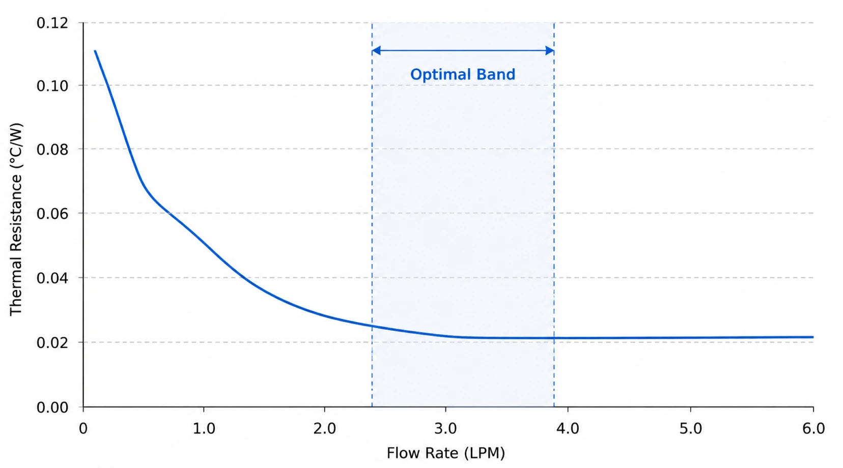
Flow rate cuts thermal resistance with sharply diminishing returns. Doubling flow from 1.0 to 2.0 LPM typically reduces thermal resistance by 25 to 35 percent, as the boundary layer thins and flow turns turbulent. Above 3.0 LPM the gain falls below 10 percent per doubling, while pressure drop, and with it pump energy, climbs quadratically. Sensitivity analysis across dozens of cold plate CFD studies converges on 2.5 to 4.0 LPM as the optimal band for GPU duty. The system-level lesson lands on the pump specification: the loop must deliver that flow against a pressure drop dominated by the cold plates themselves, hold it stable as parallel branches multiply, and do it continuously. Seal-less magnetic drive circulation pumps with stable low-flow head, such as the MDW series, match this duty profile, with the loop-level engineering covered in the AI data center liquid cooling pump selection guide.
Material Choice: When Copper Earns Its Cost
Copper conducts at roughly 400 W/m·K against 167 to 220 for aluminum, and replacing an aluminum base with copper cuts base conduction resistance by nearly 60 percent. That advantage matters above about 50 W/cm², where spreading resistance is significant, and matters little for diffuse loads below 20 W/cm². Construction method decides as much as alloy: skived-fin plates cut fins directly from the base, eliminating the interface resistance of bonded constructions; brazed assemblies seal complex channel shapes hermetically; nickel plating protects copper wetted surfaces against the loop chemistry. The plate's mounting flatness, commonly specified to 0.05 mm, controls TIM bondline thickness and quietly sets the first resistance in the chain.
The Roadmap Beyond the Cold Plate
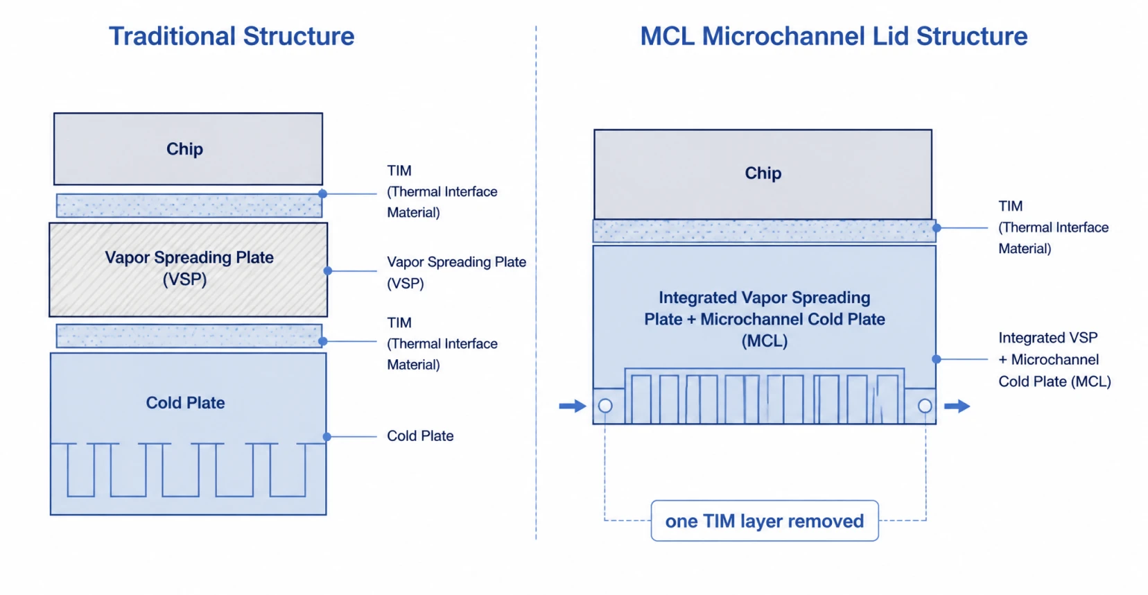
Package roadmaps past 3,000 W are forcing the architecture itself to evolve. The microchannel lid (MCL) merges the heat spreader and cold plate into one piece, deleting an entire TIM layer from the stack and shortening the heat path; the industry expects it to become the mainstream answer for ultra-high-power chips from around 2027, while conventional cold plates continue serving memory and power components. TIM technology climbs in parallel, from graphite films near 20 W/m·K toward indium-based interfaces above 80 W/m·K. At the research frontier, in-silicon microfluidics etches channels directly into the die substrate: Microsoft has demonstrated cooling up to three times more effective than cold plates with this approach, and TSMC's IMC-Si program pursues the same direction, with commercial deployment realistically beyond 2030 as leak integrity and yield challenges work through. Each step on this roadmap removes another layer between heat and coolant, and each step raises the stakes on the circulation equipment that keeps coolant moving through ever-finer channels.
What Cold Plates Demand from the Loop Around Them
- Filtration discipline: microchannels below 100 microns make coolant cleanliness a reliability variable, with side-stream filtration protecting the channels over the maintenance interval.
- Stable pressure: parallel cold plates share a manifold, and flow stability across branches depends on a pump curve that holds head as conditions change.
- Chemistry compatibility: plate metallurgy, plating, and TIM assembly all constrain the coolant specification, which is why OEM material whitelists exist.
- Pressure drop honesty: the cold plate dominates the loop's pressure budget, and its value at design flow must come from the OEM datasheet, as covered in the CDU architecture guide.
Aulank Pump manufactures seal-less vortex magnetic drive pumps for direct-to-chip cooling loops, delivering stable head against microchannel resistance with zero-leakage containment and water-glycol capability across the full operating envelope. Send us your loop flow and pressure drop data, and our engineering team will return a matched pump with the sizing calculation. Contact us for engineering support.